Letís have a project defined by a list of activities and their immediate predecessors (Task Dependency Table).
| Activity (Task) | Predecessors |
| A | |
| B | |
| C | A |
| D | A |
| E | C,D |
| F | B,E |
| G | B |
| H | G |
Activities A and B have no predecessors, so they can begin immediately. However, Activity E can't start until both Activity C and Activity D have been completed and so on. Let's construct the AOA network for this project. Note, that you can't start an activity leaving a node until all of the activities entering that node have been finished.
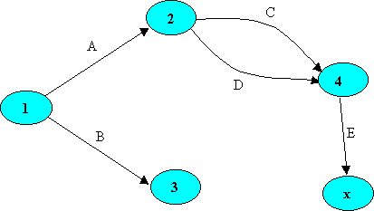
Step 1: Letís construct the first partial part of the project (exactly according to the task dependency table).

Each node represents an event, the starting or finishing
of an activity. Node 1 is the project starting event. Node 2 is the event
at which Activity A is finished. Activity A is Arc (1,2). Because the arc
for Activity C begins at Node 2, Activity A must be finished before Activity
C starts. There are two arcs connecting Nodes 2 and 4, corresponding to
Activities C and D. You can't tell which activity Arc (2,4) represents.
You
can't have two arcs connecting a pair of nodes, so we introduce a dummy
node to eliminate the confusion.
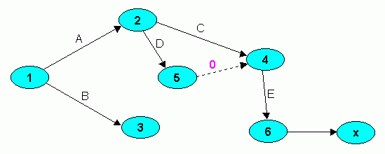
Step 2: Letís construct the second
partial part of the project introducing a dummy node.
The following picture shows the network after adding a dummy node, numbered Node 5. The dotted line from Node 5 to Node 4 represents a dummy activity that takes no time. The dummy activity's time, 0, appears on the arc. We introduced the dummy activity nodes to eliminate ambiguity. The new network still requires finishing A before starting C, finishing A before starting D, and finishing both C and D before starting E.

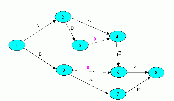
Step 3: Letís
construct the complete network of the project
Activity B be represented by an arc from Node 1 to Node 6. If it were, when Activity G's arc left Node 6, the network would require that both E and B be finished. But the precedence list requires finishing only B before starting G. Again, we introduce a dummy arc to give the correct precedence relationships (see following picture).

The complete AOA network model network
model represents the precedence requirements for all activities in. We
introduced two dummy arcs and a dummy node. Many times, you don't have
to use dummy arcs or nodes.
Fortunately, when using project management
software, you only input the list information and the software creates
the network model. New professional software but mostly uses AON project
network representation.